Bitopan Das, Polash Pratim Dutta, Monoj Bardalai , Partha Pratim Dutta
Department of Mechanical Engineering, Tezpur University, Napaam, Assam, India.
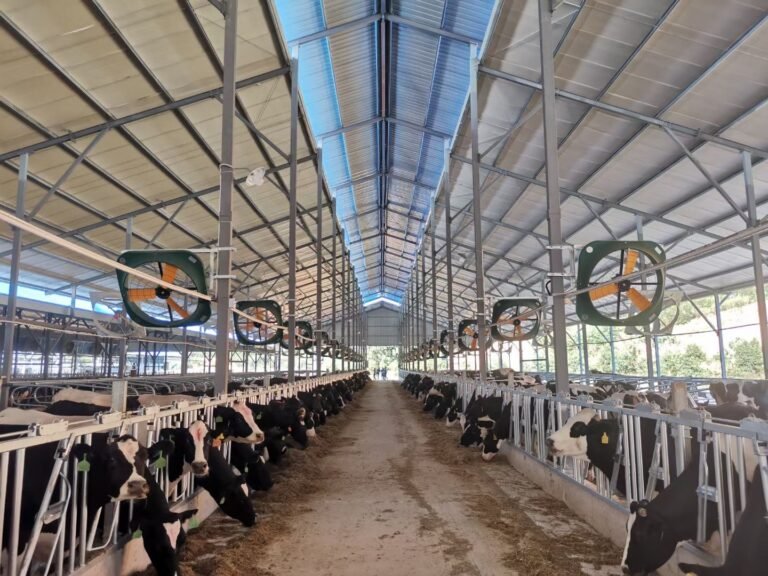
Proper ventilation in dairy barns is important in the summer as high temperatures and the accompanying heat stress can affect the health of the livestock. Although, high speed fans have been in use for a long time to cater to the needs of cooling, HVLS (High Volume Low Speed) fans have proved to be worthy of attention. The cooling effect of the large diameter HVLS fans were compared with that of high speed conventional drum fans in a simulated space using CFD models of the setups at their respective high rotational speeds. This particular work employs MRF (Moving Reference Frame) technique within the CFD simulation. The performance of both these setups were analysed at different heights and distances in order to meticulously compare the performance of the two setups more accurately. The air velocities from the HVLS fans were only slightly less than the high speed drum fans at a distance of 1 m while at increasing distances, the HVLS fan remained more effective than the high speed fans. Also, the HVLS fans covers larger area with more uniform airflow than the high speed fans.
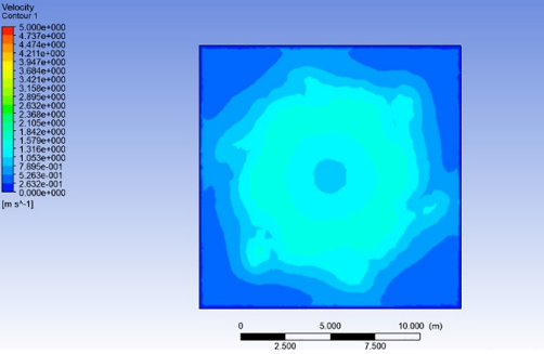
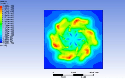
The residues reaching 103 were considered as the convergenceof the solution. In the case of the HVLS fan, in the region directlybelow the fan, the velocity at the tip is greater than at the centrewhich creates a region of high pressure near the tips and a lowpressure zone towards the centre as seen in Fig. 5. This observationhas also been made by Yan et al. [11], something which arises outof the size of the fan. The air which is sucked into the hub of the fanis forced away by the blades which reaches the floor and then loopsacross the room to move back towards the fan. Fig. 5 shows thevelocity contour in a plane through the middle of the fan and alongthe height of the room. In the region immediately below the fan, airvelocities are greater than at other heights with the highest velocity being near the tips which can be seen in Fig. 6. At a distance of3 m from the floor, the air velocity ranges from 1.6 m/s directlyunder the fan to 1 m/s in the remaining area (Fig. 7). At the planeof 2 m from the floor, the airflow distribution remains smoothenedout with the average velocity across the room being 1.42 m/s(Fig. 8). On a plane at 1 m from the floor which can be seen inFig. 9, the velocity of air is 1.58 m/s directly under the fan and inthe rest of the room, it ranges from 0.5 m/s to 0.8 m/s. The airvelocity at 1.5 m from the floor is quite uniform with an averagevelocity of 1.3 m/s. For validation, these results were comparedwith the experimental work done by Worley et al. [7] in whichthey found that air velocities in the regions close to a single HVLSfans ranged 0.441.7 m/s. At a height of 1 m from the floor, whichis typically the breathing height, the results were in accordancewith the experimental work of Worley et al. [7].
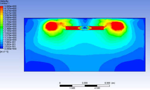
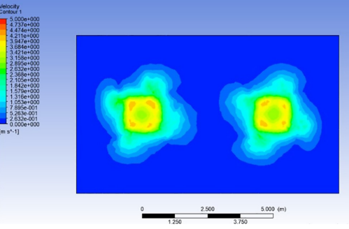
The high speed drum fans are placed at 5 m apart, each at theheight of 2.5 m from ground (Fig. 10). The velocity in the planeclose to the fans are higher as expected with the highest velocityof 3.9 m/s as compared to other regions in the room. At a distanceof 0.5 m from the fans as seen in Fig. 10, the distribution from thetwo fans is symmetric with maximum velocity of about 3.1 m/s inthe region lying along the fan’s axes. The velocity on the plane at adistance of 1 m from the fans are more uniform as seen in Fig. 11with an average velocity of 1 m/s. As the plane is moved beyond1 m, the average velocity drops significantly as well as the areaof influence. For example, at the distance of 1.5 m from the fansas seen in Fig. 12, the maximum velocity is only about 0.8 m/s.Thus, it can be seen that the air velocity of the high speed drumfans required for cooling remain effective only up to a small distance, beyond which additional number of fans are required inorder to maintain comfort level. These directional fans when compared with the HVLS fans, it is found that air is blown at high velocity near the fans, but the cooling effect declines with distance. Also,HVLS fans have more uniform airflow at any plane from the floorcompared to the directional fans. Moreover, the high noise generated by the fast moving drum fans prefers the HVLS fans excel as abetter alternative. HVLS fans can provide a cooling effect similar tohigh speed fans although the average velocities are not higher than the latter type. With the benefits of low energy consumption, less noise and a more uniform airflow, HVLS fans can provide reasonable comfort to the livestock.
A comparison of HVLS fans and high speed drum fans for the use during summer in dairy barns was done using CFD analysis. In this study MRF technique was coupled with CFD simulation. The fans were run in a simulated space at 90 rpm and 500 rpm respectively. The HVLS fan had a more uniform airflow at the breathing height. This study attempted to measure the air velocities at set distances and compared the performances of the two setups accurately. The average velocity of the HVLS fan did not outdo that of the two high speed drum fans but had similar results. The highest air velocity from the HVLS fan at a height of 1 m was 1.58 m/s while that of the two high speed drum fans at 1 m distance was 1.7 m/s. Although at close distances, the high speed fans provided better airflow, the cooling effect at increasing distances were significantly lower making them suitable only when used in more numbers in a large space. The operational output of the HVLS fans being close to that of the conventional high speed fans while being more energy
efficient promises HVLS fans as a good alternative cooling method. Also, HVLS fans generate less noise along with a bigger area of coverage thereby eliminating the need for frequently repetitive rows
of conventional high speed drum fans.